
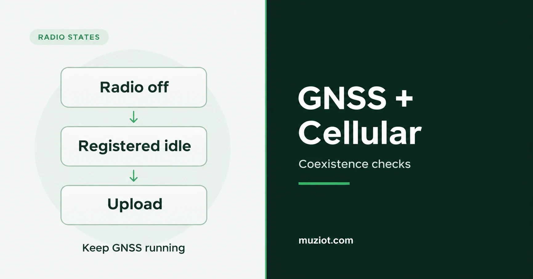
If your tracker loses GNSS signals when a cellular upload starts, record both events on the same timeline. Keep the GNSS receiver running while you compare cellular states. Moving an antenna, changing the power supply and restarting the receiver together makes the result difficult to interpret.
On a terminal with a separate GNSS receiver and cellular modem, trace the receiver’s RF path and shared supply connections. Start by identifying what the GNSS receiver actually loses.
Identify what changes at the receiver
A position jump, fewer tracked signals and a change from RTK fixed to float need different follow-up checks. Save the receiver’s raw output around the event. Record signal or satellite identifiers, available carrier-to-noise-density ratio (C/N0) readings, tracking and solution status, and any restart or communication gap.
For an RTK receiver, record correction delivery too. An interrupted correction stream can change the solution status while satellite reception continues. Use the NTRIP and RTCM integration guide to trace that path before treating every loss of RTK fixed status as RF interference.
Compare the same satellite and signal where practical. A single average can hide a problem affecting one band, while changing sky conditions can make observations from different times difficult to compare.
Separate interference at GNSS frequencies from strong nearby transmitters
The ZED-F9P integration manual, section 4.6, distinguishes two interference paths. Emissions within a GNSS band compete directly with reception. Strong signals outside the band can drive the receiver’s RF front end into nonlinear operation, reducing sensitivity or producing interference through intermodulation.
Check the cellular transmitter alongside digital clocks, displays, interfaces and power circuits. Their activity can change during the same upload. Pair the RF investigation with host-workload and supply records.
Draw the path from the GNSS antenna to the receiver input. Mark any antenna amplifier, cable, connector, filter and bias supply. The u-blox GNSS antennas application note, section 6, discusses strong transmitters, digital noise and front-end compression. Use that distinction to decide which part of the path to inspect.
Compare cellular states without restarting GNSS
Fix the antenna positions and leave the receiver configuration unchanged for the first comparison. Record the enclosure state, antenna and cable parts, receiver firmware and modem firmware. Add the cellular band and channel information available from the modem.
Compare the following three cellular states.
Scroll sideways to read all columns.
| Cellular state | Record during the comparison |
|---|---|
| Radio disabled using the modem’s documented control | Control state, remaining host activity and the GNSS baseline. |
| Registered, with no user traffic task | Registration state, background activity and any GNSS changes. |
| A repeatable uplink traffic task | Task start and end, available cell information, GNSS output and supply behaviour. |
A registered modem can still transmit without an application upload. Label the idle run by its observed state. When you have measurements of actual transmitter activity or power, keep them beside the traffic log; a queued software transfer is a different observation.
Repeat the sequence, including a return to the baseline. Align the GNSS, host and modem logs to a common time reference, or record the offsets between their clocks.
Change one physical path, then repeat the sequence
For an external antenna comparison, change the GNSS antenna’s position relative to the transmitting antenna. Keep its height, orientation, ground-plane arrangement and cable chain as consistent as the installation allows. Record both positions and restore the first arrangement for a return check.
A relocation also changes the GNSS reception environment. Compare the signal records alongside the cellular timeline, including the return run. An improvement during a different sky view or satellite geometry needs a narrower comparison.
If you investigate filtering, identify the unwanted frequency range and the amplifier or receiver stage that needs protection. Check the filter’s wanted-band loss and the resulting gain budget. The GNSS antenna selection guide covers receiver bands and the complete antenna-to-receiver path. Use the component documentation to choose the filter location and ratings.
Inspect the supply and return paths separately. Capture voltage at the GNSS receiver and check its antenna bias supply during the upload. Look for receiver restarts and host-interface gaps in the same interval. Follow the power-supply measurement approach when the symptom follows a supply disturbance.
On the PCB, review RF routing beside digital circuits, shielding and ground-current paths. Test one routing, shielding or layout hypothesis at a time and retain the original configuration for comparison.
Choose the next check from the observed change
Choose the next check based on what changed.
Scroll sideways to read all columns.
| Observation | Next check |
|---|---|
| The same GNSS signals weaken repeatedly during uploads | Compare RF coupling, transmitter conditions and band-specific behaviour. |
| The receiver restarts or its output stops | Inspect receiver power, reset indications and the host data path. |
| RTK status changes while signal tracking remains similar | Check correction arrival and receiver status alongside the RF logs. |
| Results drift between runs without a consistent cellular relationship | Review sky view, geometry, timing and other changing loads before altering more hardware. |
Use the product’s tracking and positioning requirements to define acceptance. Keep the original logs even when a comparison looks convincing. Reproducing a change helps narrow the cause; locating it in a particular RF stage may require further measurements.
For a ZED-F9P design, review the integration manual’s interference-monitoring section and use the interface description for the installed firmware to interpret diagnostics. Save the raw diagnostic output with the signal records.
Send a repeatable record for design review
Include a sketch of the RF path and antenna positions, the board revision, receiver and modem firmware, and the exact change between runs. Pair the receiver logs with the traffic timeline and power captures. State the required tracking or positioning behaviour and which observation failed it.
Use the ZED-F9P product reference to identify the receiver suffix, and carry the coexistence constraints into the wider cellular module selection process. When requesting documents through the Datasheet Center, include those identities and the RF-path sketch so the supplier can return the applicable design guidance.
Sources
- u-blox, ZED-F9P Integration manual, UBX-18010802 R16, October 30, 2024: sections 3.14.2, 4.4, 4.6 and 4.7.1.
- u-blox, GNSS antennas: RF design considerations for u-blox GNSS receivers, UBX-15030289 R03, October 16, 2019: section 6.