
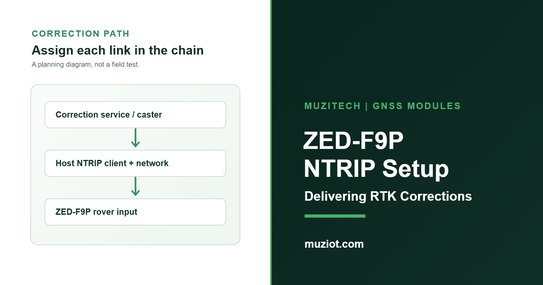
An RTK rover needs more than a GNSS receiver and an LTE modem. It needs a suitable correction stream, a host that can obtain and forward that stream, and a receiver configured to accept it. NTRIP carries correction data across the network; RTCM is the correction format delivered to the rover. A cellular module can provide the network connection, but it does not supply an NTRIP subscription or turn the ZED-F9P into a network client by itself.
This guide is for an engineer planning a US robot, field instrument or other connected rover. It explains how to identify the receiver, assign each part of the correction path and record whether the resulting position solution works. It does not give universal configuration keys or promise an RTK fix: those depend on the exact ZED-F9P version, firmware, correction service, antenna installation and site.
Verify the exact receiver and firmware
Start with the ordering code on the part offered for the project, not the photograph on a product page. Muziot's ZED-F9P product page labels its reel photo ZED-F9P-01B-01, while the retained download is a ZED-F9P-05B data sheet. These identify different revisions. The photograph does not establish what a future quote will supply or what firmware a photographed unit runs.
The u-blox 01B data sheet R09 identifies ZED-F9P-01B-01 with HPG 1.12. The ZED-F9P-05B data sheet R02 identifies ZED-F9P-05B-00 with HPG 1.51. The u-blox integration manual R16 covers both in its applicability table. That cross-version manual is useful for the architecture, but a feature or default listed for 05B cannot simply be assigned to an 01B unit.
For an HPG 1.51 unit, u-blox publishes an Interface Description R01 for interface 27.50. Its FW 1.00 HPG 1.51 release note points to the matching interface and RTCM 3.4 documentation. These are version-specific references, not evidence that a photographed or future supplied receiver runs HPG 1.51, nor a recommendation to flash unknown hardware. Use a matching interface description for an actual HPG 1.12 unit rather than copying 1.51 setting names.
| Item to record | Example of a matching document | Decision before configuration |
|---|---|---|
ZED-F9P-01B-01 | 01B data sheet R09; HPG 1.12 applicability | Use the interface description and settings for the actual 01B firmware |
ZED-F9P-05B-00 | 05B data sheet R02; HPG 1.51 and interface 27.50 applicability | Use the 05B message and HPG 1.51 interface documentation if the unit runs that firmware; do not transfer its newer functions to 01B |
| Quoted item not yet fixed | No version can be assumed from a series page or image | Obtain the exact orderable suffix, firmware and matching document set |
Ask for the receiver's reported firmware and configuration backup from the actual evaluation unit when a project begins. If that unit has been updated, use documents that apply to its installed firmware. Until the variant is fixed, this article can define the path and evidence to collect, but it cannot be a click-by-click device profile.
Map the correction path
Draw the path before changing receiver settings. A reference station or correction network produces data. An NTRIP caster exposes a selected stream or mountpoint. A host computer, gateway or controller runs the NTRIP client and connects to the caster over an available network. The host then forwards the appropriate RTCM messages to an enabled input on the ZED-F9P rover. The rover's navigation solution is the final observation point.
Reference station or correction network
          -> NTRIP caster / selected mountpoint
          -> host NTRIP client over LTE, Wi-Fi or Ethernet
          -> selected receiver input carrying RTCM
          -> ZED-F9P rover and position output

Optional for a service that requests rover position:
ZED-F9P NMEA GGA -> host NTRIP client -> caster
Diagram caption: An original responsibility map. The arrows show data direction only; they do not show tested latency, coverage or positioning accuracy.
Identify who supplies each element. The correction provider supplies access terms and a stream appropriate for the geography and receiver. The network provider supplies connectivity at the deployment site. The host integrator owns credentials, reconnect behavior and forwarding. The receiver integrator owns its input and status configuration. As a documented evaluation example, u-blox says its EVK-F9P setup uses a networked computer running u-center; u-center contains the NTRIP client/server and delivers corrections to the receiver. That example does not make a bare ZED-F9P a network client. If the caster requires a virtual reference station, the client may need to send the rover's NMEA GGA position upstream; confirm that requirement with the service instead of enabling it by assumption.
An LTE connection is one possible transport. It still needs a supported SIM and coverage at the site, and it must carry the correction stream through expected network interruptions. Neither a ZED-F9P data sheet nor a modem product page proves that a specific caster, account, mountpoint or cellular plan works in a customer's device.
Route RTCM and optional GGA
Match the incoming stream to the exact receiver documentation. The 05B R02 data sheet lists RTCM 3.4 message types accepted by a ZED-F9P-05B rover; it also lists messages a base station can output. Those are different roles. Do not use the 05B list as an unchecked 01B compatibility table. For an 01B unit, use its matching data sheet and interface description. Ask the correction provider which message types and reference frame its mountpoint sends, then compare that list with the receiver and project requirements.
Choose one physical receiver input supported by the selected hardware and firmware. Configure the host and receiver to use the same transport and, for a serial link, the same baud rate and framing. Enable the appropriate protocol on that input using the matching interface description. Keep a copy of the prior receiver configuration and record every changed setting so the setup can be reproduced or reversed. A port that passes bytes is only the first check; the rover must also accept usable corrections.
Bring the path up in a deliberate order: confirm network connectivity, authenticate the host client to the intended mountpoint, observe correction bytes at the host, confirm those bytes reach the selected receiver input, then inspect the receiver's navigation status. Where the provider requires GGA, verify its reverse route separately. A successful caster login does not by itself prove that the receiver has reached an RTK float or fixed solution. The exact diagnostic messages, fields and setting names must come from the chosen firmware's interface description, not from a generic screenshot.
For a mobile rover, repeat the observation after a short network interruption and after moving into a different coverage condition. Record the time to reconnect and whether correction data resumes. The article supplies a test sequence; it does not report that any specific product combination has passed it.
Log the solution and outages
A useful log connects each position result to the stream and hardware that produced it. Capture the receiver ordering code and firmware, host software version, antenna installation, correction service and mountpoint, transport and selected input, timestamps, network mode and receiver status. Record correction age and fix state if the selected receiver output exposes them, using the field definitions in its matching interface description. Do not invent a universal age threshold or infer centimeter accuracy from a label alone.
Use this blank record for a bench or field run. Replace the blanks with observations; leave a cell open when a source or measurement is unavailable.
| Field | Project entry |
|---|---|
| Date, location and run ID | ______ |
| Receiver full code / firmware / host revision | ______ |
| Antenna model, placement and cable | ______ |
| Network path, SIM or Wi-Fi profile | ______ |
| Correction provider, mountpoint and reference frame | ______ (redact credentials) |
| RTCM messages and receiver input / serial settings | ______ |
| GGA return required and observed? | ______ / not applicable |
| Client connected; bytes received; receiver accepted data | ______ / ______ / ______ |
| Navigation mode, correction age and time to first usable solution | ______ / ______ / ______ |
| Outage start, reconnection and post-outage mode | ______ / ______ / ______ |
| Raw log location and reviewer | ______ |
Table caption: An original, unfilled integration log. Blank cells are requested evidence, not measured results.
If the client receives bytes but the rover never improves its solution, work from the first failed boundary: mountpoint contents, host forwarding, enabled receiver input, message support, antenna view and service coverage. A position status alone cannot identify which boundary failed. Preserve the raw logs and the exact document versions used to interpret them.
Prepare the integration request
For a supplier or design review, send the full ZED-F9P suffix, reported firmware, intended US locations, antenna and host board, available receiver input, network device and correction service requirements. Add expected quantity and whether the request is for a bare receiver, evaluation hardware or an assembled board. That lets the supplier identify matching documents and saleable items without guessing from a family name.
Muziot's ZED-F9P page is the starting product reference; use the datasheet center to request the correct revision, then send a BOM and integration requirements for the actual offered form. The quote must confirm the exact part and documentation. A correction subscription, site coverage, receiver settings and device-level performance remain project decisions. For a broader GNSS and cellular duty-cycle discussion, see the separate asset-tracking article; this guide focuses on the correction path and its evidence.