
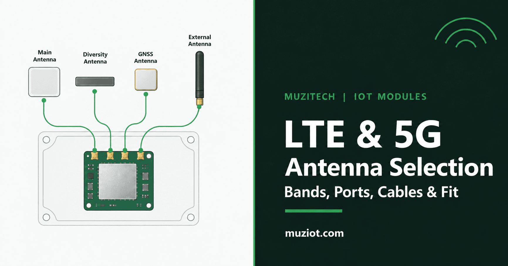
An antenna cannot be selected from its shape alone. For a US IoT device, start with the networks and bands the finished product must use, the exact cellular module and host board, and every RF port that the design needs. Then compare antenna coverage, mounting space, feed cable, and the complete connector pair. The final decision comes from testing the assembled device, not from a free-space antenna chart.
This sequence matters whether you are designing a compact sensor with an internal antenna or an outdoor gateway with external antennas. It also keeps a module selection decision separate from an accessory purchase. A module product page may identify antenna connections without specifying the antennas, cables, or carrier board supplied with an order. Our cellular module selection guide covers the wider module shortlist; this guide focuses on the RF path after that shortlist exists.
The five decisions to record before ordering
| Decision | Record for the actual design | Why it matters |
|---|---|---|
| Radio scope | Country, intended operator or private network, LTE/5G modes, required bands and module ordering code | A broad "5G" label does not identify the bands your device will use. |
| RF ports | Module and host-board revision, port labels, port purpose and required antenna count | Main, diversity, MIMO and GNSS paths must not be treated as one interchangeable socket. |
| Antenna | Exact antenna part number and document revision, frequency coverage, mounting and ground-plane requirements | A family brochure or a visually similar part is not an exact-part approval. |
| Feed path | Cable type, length, loss by frequency, adapters and the two mating connector part numbers | Cable and transition losses can offset the benefit of moving an antenna. |
| End device | Enclosure material, antenna location, nearby metal, installation orientation and test conditions | The installed radio path can behave differently from the supplier's reference setup. |
This worksheet records design inputs, not measured antenna performance. Fill it with the exact parts and conditions of your own device; an empty cell is not a pass result.
Start with the bands and ports the device will actually use
Ask the network owner which bands and modes matter at the planned US deployment locations. Match that list to the exact module variant and firmware, then to a candidate antenna's documented operating ranges. Do not infer coverage from the words "LTE," "Sub-6," or "global" on a package. A range printed for one antenna element in a combination enclosure may not describe its other elements.
Next, draw the RF path from each module port to the final radiating element. A 5G MIMO design may need several distinct cellular paths. GNSS, where present, is a separate receive path with different antenna requirements. Use the module's applicable hardware design guide and the actual carrier-board schematic to map port labels. For example, the Quectel RM520N-GL product page describes four Sub-6/GNSS antenna connections for that M.2 module. Quectel's RM520N Series Specification V1.6 lists four connections for the GL variant and four plus one optional connection for the EU variant. The suffix therefore belongs in the RF worksheet. The product page also states that antennas, cables and a carrier board are not implied by the module photographs. Neither document establishes a mating connector or approved antenna for a particular host-board revision.
Two exact-model Quectel datasheets illustrate why the RF worksheet needs more than a "5G antenna" label. The released YF0017GA V2.1 sheet specifies an adhesive embedded FPC antenna, 1100-6000 MHz, a 201 mm cable, and an IPEX MHF 4L termination. Its stated range does not include sub-1100 MHz cellular bands. Its evaluation-board and free-space results do not establish performance inside a customer's enclosure. The released YEMX425J1A V2.1 sheet describes a four-element external assembly with four SMA male terminations and pole, wall, or suction mounting. Its cover specifies three frequency ranges: 410-470, 617-2690, and 3300-6000 MHz. The mechanical table specifies 450 mm ALSR200 cables, while the overview discusses 500-5000 mm options; confirm the ordered cable configuration before estimating loss. Neither SMA male nor MHF 4L names the receptacle or adapter on a particular host board. These are documented design examples, not Muziot stock or approved device pairings.
YEMX425J1A V2.1 includes GNSS reference tests labeled RM520N-GL, but its port-correspondence table labels the module "RG520." That difference must be clarified with Quectel before using the table as an RM520N-GL port map. The reference tests are not measurements of the reader's final device.
Choose embedded or external placement around the enclosure
An embedded antenna can save an external mounting step, but its performance depends on the PCB, ground plane, nearby components and enclosure. An external antenna can move the radiating element outside a metal cabinet or away from interference, while adding a cable run, an opening, weather sealing and installation work. Neither category wins by default. Compare each option in the actual mechanical design.
For an embedded candidate, document the supplier's keep-out and ground-plane conditions, the available PCB edge or enclosure location, and what changes when the battery, display, shield or cables are installed. For an external candidate, document the mounting surface, cable exit, bend and strain relief, connector access, sealing method and installed orientation. Do not assume a printed environmental rating still applies after a different hole, gasket or cable entry is used.
Placement, ground plane and cable routing should be tested in the actual enclosure; a vendor reference setup does not predict the finished device. If the host itself is still being chosen, our LGA, M.2 and Mini PCIe guide explains why the module package and the board assembly must be identified separately.
Account for cable loss, connectors and mounting
An antenna's published gain does not tell you the loss of the installed feed. Obtain the selected cable assembly's insertion loss at the relevant frequencies and at its ordered length. Add the documented losses of any adapters and other RF transitions. Record the measurement reference points so a bare-antenna figure is not compared with a full-cable assembly figure. A longer cable may improve placement and increase feed loss at the same time; compare the complete paths rather than choosing by cable length alone.
Treat the connector as two named parts: the receptacle on the exact module or carrier board and the plug on the exact cable. Marketing labels such as "IPEX" or "MHF" are insufficient to prove mating. Verify the manufacturer's series, part number, gender, cable size and assembly drawing for both sides. A connector that looks close in a photo can still be the wrong series or height. Do not force a sample connection to resolve a documentation gap.
For a panel or external antenna, check mounting thickness, thread and fastener specification, torque instructions, sealing stack, minimum bend radius and cable strain relief against the vendor's current drawing. For an adhesive or internal antenna, verify surface preparation, placement clearance and repeatability in assembly. Record the final configuration before RF testing; a later enclosure or cable change may require a retest.
Validate the antenna system in the finished device
Create a test matrix for the intended network modes, bands and installation orientations. At a minimum, identify the module ordering code and firmware, host-board revision, antenna and cable part numbers, enclosure build, SIM or network profile, test location, instrument, calibration state and acceptance criteria. Measure the RF characteristics appropriate to the design with a qualified RF team. Compare cellular registration and application behavior under the same controlled conditions for each candidate. For MIMO, preserve the port mapping when evaluating the assembled system.
The results should say exactly what was tested. A vendor reference plot, a bench setup with an open enclosure, and a finished-device result are different evidence. Do not turn a single signal reading into a throughput or coverage promise. If a candidate fails, change one documented variable at a time, such as placement, cable assembly or matching network, then retest. Keep the unsuccessful configurations in the engineering record so procurement does not accidentally order an earlier version.
For a quote or technical review, send the exact module P/N, host board revision, target US network and bands, enclosure drawing, antenna candidate P/N, cable length and the required port map. The RM520N-GL module page and our Datasheet Center are starting points for module documents. If the accessory is still undecided, send the BOM and application details and ask for a module-and-antenna matching review. The exact antenna, cable and supplied items should be confirmed in the quotation and then validated in your finished device.