
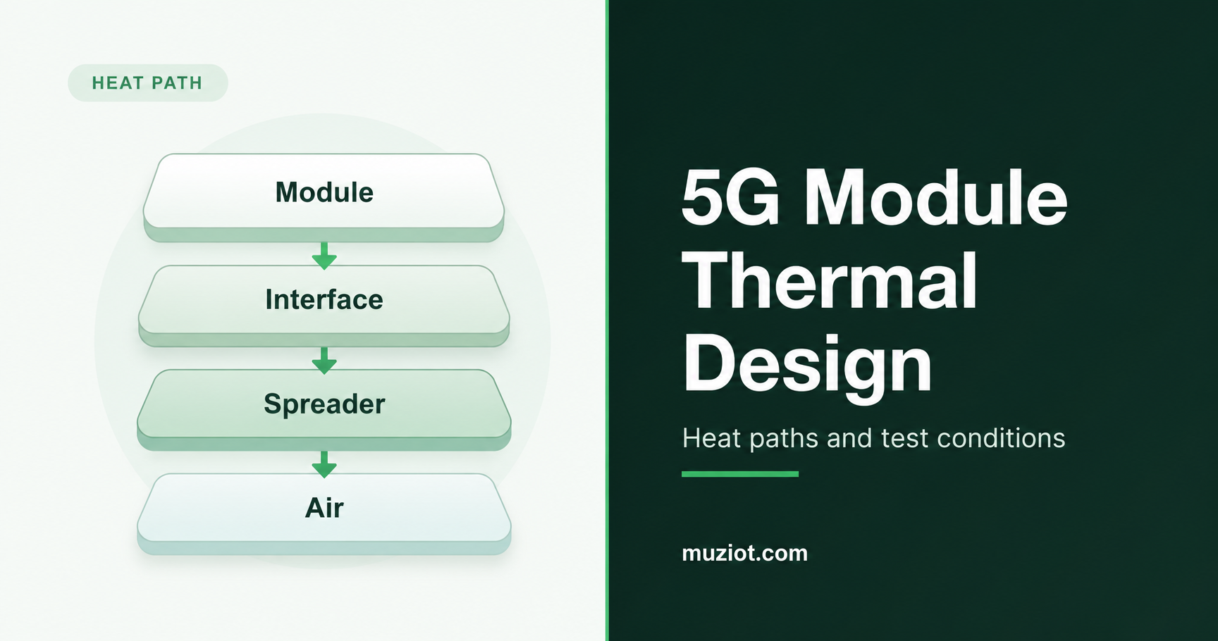
A 5G gateway can finish a short download on an open bench and still slow down once its enclosure is closed. Before choosing a pad or heat sink, work out how heat will leave the finished product during sustained use. The module, carrier board, interface material and enclosure all affect that path.
The example here is an M.2 cellular module. For module selection and mounting choices, see the cellular module selection guide and form factor guide.
Start with the workload and installation
A gateway inside a cabinet faces different cooling conditions from one on an open desk. Specify the highest intended ambient temperature, mounting orientation and ventilation, along with nearby heat sources such as the processor, voltage regulators and other power-conversion stages.
The workload matters too. Sustained uploads, downloads, simultaneous traffic and idle periods put different demands on the assembly. Include the host’s work: packet forwarding and application processing add heat that an idle test computer may not reproduce.
Before testing, agree on the required sustained data rate, connection stability and applicable component and product temperature limits. Get the module’s thermal monitoring and protection information for the proposed firmware so you can interpret its readings and events during the run.
Trace heat from the module to the air
A pad transfers heat into the part it touches. That part still needs a route to the surrounding air. Trace the contacts from the manufacturer’s approved module surface, through the thermal interface material, into a spreader or enclosure, and out to the environment. Include the mounting structure that holds those contacts together.
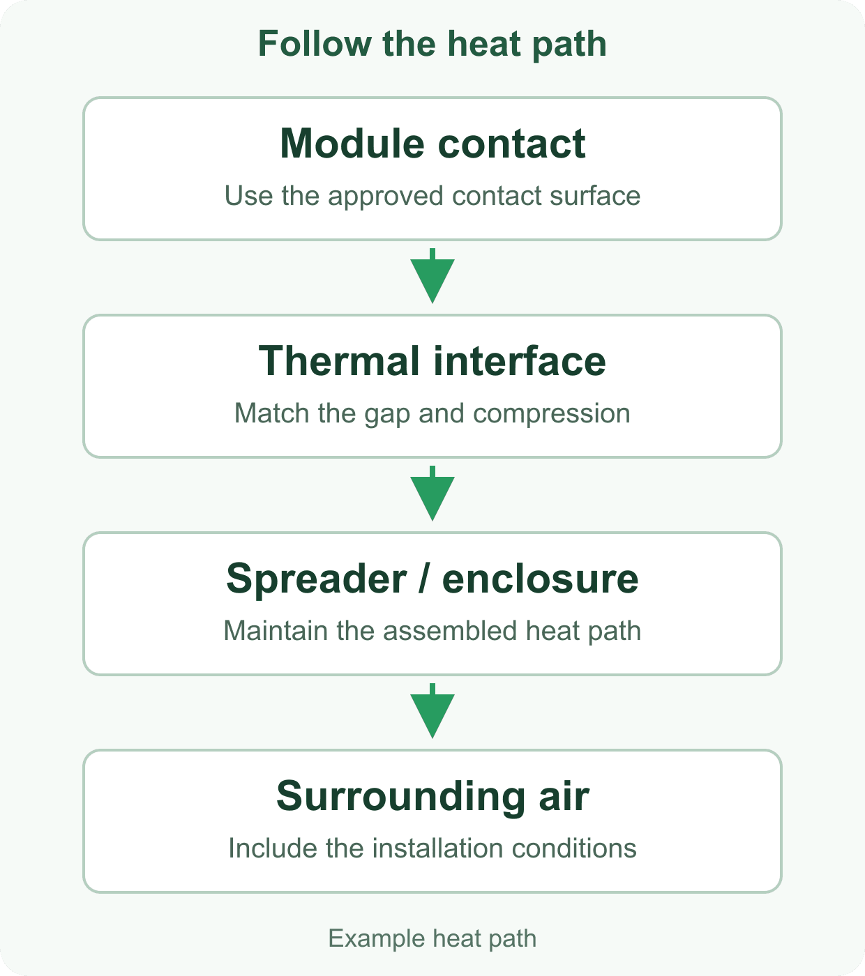
Use the module’s hardware guide to check the proposed contact surfaces. Section 6.5 of Quectel’s RM520N-GL Hardware Design V1.0 discusses thermal dissipation and its effects on RF output power and data rate. Request the guide and mechanical drawing that match the module revision you plan to integrate.
Then follow the heat beyond the spreader. Inside a sealed plastic box, it may spread a hot spot across the assembly while the enclosure continues to warm. If a metal case serves as the heat sink, its external surface temperature also needs review. Test with the intended mounting face, surrounding equipment and airflow.
Choose the pad for the assembled gap
Start with the gap in the closed assembly. Quectel lists the RM520N series as an M.2 design measuring 30 mm x 52 mm x 2.3 mm. Those dimensions describe the module outline. Pad fit also depends on the socket height, carrier, fasteners, mating surface and their tolerances.
Conductivity is one part of the material choice. Henkel’s GAP PAD HC3000 product information also lists compliance, compression stress and thickness. Check how the material conforms to the contact surfaces at the intended compression, and how much load it transfers into the board and module.
Mechanical details to resolve before ordering the interface.
Scroll horizontally to read all columns.
| Design item | Information to collect | Decision to record |
|---|---|---|
| Gap and tolerance | Closed assembly dimensions, variation and mating-surface flatness | Material thickness and permitted compression across the tolerance range |
| Contact area | Manufacturer-approved surfaces, nearby components and keep-outs | Pad shape and placement on the actual module revision |
| Mounting load | Standoffs, fasteners, support and material compression data | How the assembly maintains contact without overloading the module or carrier |
| Installation clearance | Antenna cables, connectors, service access and airflow space | Clearances retained after the enclosure is closed |
Inspect the contact after fastening the enclosure. A pad that fits the nominal drawing can still leave a gap or bend a lightly supported board. Check antenna cable routing at the same time; the antenna selection guide covers the related RF installation checks.
Put temperature and throughput on one timeline
Label each temperature channel by its sensor and location. Keep ambient air, enclosure surface, board probes and module-reported values in separate columns. For a software reading, include the command or tool, firmware version and the manufacturer’s sensor description.
TI’s Semiconductor and IC Package Thermal Metrics explains how junction and surface temperatures differ, and why package thermal parameters depend on measurement conditions. In the modem log, identify a surface measurement as such; it does not establish the temperature of every IC inside the module.
Channels to align on the same test timeline.
Scroll horizontally to read all columns.
| Channel | Record | Why it helps |
|---|---|---|
| Environment | Ambient probe position, air temperature, orientation and ventilation | Establishes the cooling conditions for the run |
| Assembly temperatures | Named surface/board probes and exact measurement positions | Shows how the assembly warms during the workload |
| Module telemetry | Supported sensor readings and thermal/protection events | Connects firmware observations to the temperature trend |
| Traffic and radio | Upload/download rate, traffic pattern, network mode, band and signal readings | Helps distinguish cooling changes from radio or traffic changes |
| Host and supply | CPU load, supply voltage/current and disconnect/reset events | Identifies other changes that may affect the same run |
When throughput falls, compare the timing with temperatures, protection events, radio conditions and host load. A serving-cell change, server limit or host bottleneck can also reduce speed. The shared timeline helps you decide which condition to investigate in the next run.
Test the closed enclosure
A short bench run can check the probes and traffic generator. The cooling decision needs a test of the closed product in its intended installation.
- Fix the configuration for each run. Record the module variant and hardware revision, firmware, carrier, enclosure, interface material, fastening arrangement, antennas and host software.
- Make the setup repeatable. Photograph probe locations and cable routing. Note the supply, traffic endpoint, network conditions and logging intervals, then synchronize temperature and performance timestamps.
- Use the same starting conditions. Begin comparisons at the same ambient temperature and assembly state, with the enclosure closed and in the specified orientation.
- Run the product’s workload. Exercise traffic and host tasks together for the duration in the test plan. Capture warm-up, sustained operation, temperature trends, protection events and connection interruptions.
- Change one cooling detail. Compare a revised contact, interface or heat-spreading arrangement while holding the other conditions as consistent as the setup permits. Keep runs with changed network conditions identifiable.
- Check the pass criteria. Review sustained operation, applicable component temperatures and the product’s surface requirements. Repeat the selected arrangement under the required environmental and installation conditions, and retain its configuration with the logs.
Include cooling details in the module enquiry
Send the module candidate, workload, ambient range, enclosure material, carrier arrangement and available cooling space. Ask for the matching hardware guide, mechanical drawing and firmware thermal-monitoring information. For an adapter or dongle, identify the complete assembly so the enclosure and interface can be reviewed together.
The RM520N-GL product page is a starting point for the module enquiry; the Datasheet Center provides technical references. Send the part list and mechanical questions through the BOM service, and keep the agreed module, interface and enclosure revisions with the test record.
Sources
- Quectel: 5G RM520N series, form factor and outline dimensions.
- Quectel: RM520N-GL Hardware Design V1.0, July 15, 2022, section 6.5. Reference revision for the thermal discussion.
- TI: Semiconductor and IC Package Thermal Metrics, SPRA953D, revised March 2024, sections 1-3.
- Henkel: BERGQUIST GAP PAD TGP HC3000, material properties and available thicknesses.
Source review: October 20, 2026.