
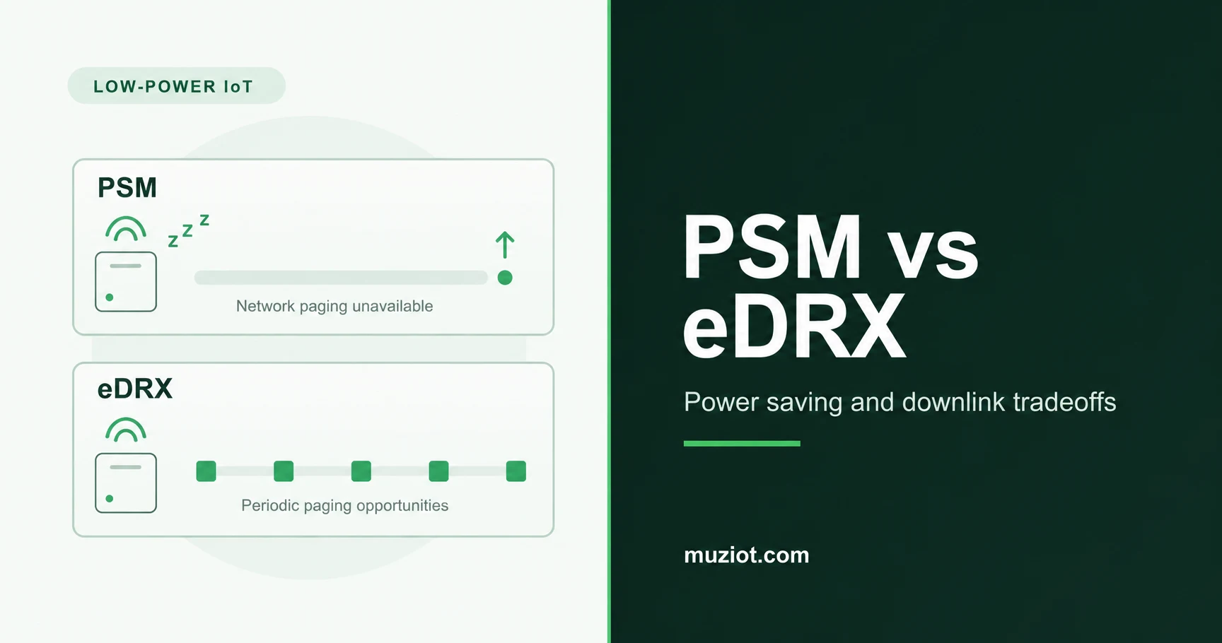
PSM saves power by making a registered device unavailable for network paging while it sleeps. eDRX creates periodic paging opportunities, trading longer gaps between them for less listening activity. Choose between them by asking when the server must reach the device, then check the timers the network actually grants.
This guide focuses on LTE-M and NB-IoT state behavior, a documented BG95 command checklist, and whole-device measurement. It does not predict battery life or confirm support on a particular operator. If you are still choosing the radio technology, start with the NB-IoT, LTE-M and LoRaWAN comparison.
Compare paging availability before comparing current
In Power Saving Mode (PSM), the device retains its network registration context but cannot receive network paging during the PSM interval. A server message cannot wake it through paging. Delivery must wait until the device leaves PSM and communication becomes possible. Quectel's PSM Application Note V1.0, section 2, describes this distinction from switching the module off.
Extended discontinuous reception (eDRX) organizes idle-mode paging into recurring paging time windows (PTWs). The device checks paging occasions within a PTW; it does not listen continuously throughout that window. Between windows, the receive path can sleep. The eDRX cycle describes the interval between consecutive PTW starts. PSM and eDRX can also be used together: eDRX can govern paging while the device is available before it enters PSM. See the GSMA Mobile IoT Deployment Guide, the PSM and eDRX sections.
Swipe the table to see all columns.
| Operating choice | Downlink consequence | Question to resolve in testing |
|---|---|---|
| PSM | No network paging during the PSM interval | Can the command wait until the next permitted wake and communication event? |
| eDRX | Paging opportunities recur within PTWs | Does delivery still meet the application's deadline across different arrival times? |
| PSM with eDRX | Periodic paging opportunities while available, followed by an unavailable PSM interval | Does the server know when to respond and when to wait? |
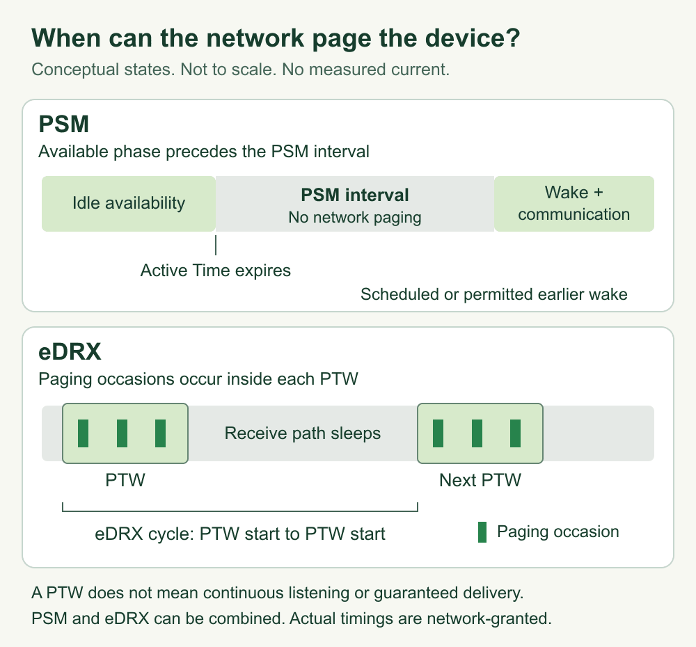
Figure 1. Conceptual state sequence, not to scale. Blocks identify availability states and paging occasions, not measured current. PSM and eDRX rows show different operating choices; a device can combine them.
Separate requested timers from network-granted timers
An accepted AT setting proves that the modem accepted a local request. It does not prove that the network granted that value, that the modem entered the intended state, or that a cloud command arrived on time.
For PSM, T3324 is the Active Time timer associated with the period of idle-mode availability after connected operation. T3412 is the extended periodic tracking area update (TAU) timer. Treat the granted T3412 as a registration-maintenance parameter, not a promise that the radio will sleep uninterrupted for exactly that duration. A permitted application-originated event can lead to an earlier wake. For BG95, the supported wake mechanism must be checked against the actual hardware form and its guide; Quectel's PSM note, section 4, describes the module mechanisms.
Keep separate columns for request, grant, and observation. Preserve raw responses as well as decoded durations. Decode bit fields using the matching manual and access technology; do not apply an LTE-M PTW interpretation to NB-IoT without checking it.
Swipe the table to see all columns.
| Record | Requested value | Network-granted value | Observed behavior |
|---|---|---|---|
| PSM T3324 and extended T3412 | Saved PSM request and raw encoding | Current network timer response | Actual entry, wake and TAU timestamps |
| eDRX cycle and PTW | Saved eDRX request; any separately configured PTW request | Current dynamic cycle and PTW fields | Paging-related activity and downlink delivery timestamps |
| Test context | Full part, board revision, firmware and host software | SIM profile, operator, APN, RAT and serving-cell context | Coverage conditions, interface state and supply measurement point |
Repeat the grant check after a registration or network change. If a response is absent, reports no eDRX use, or differs from the request, record that result. Do not replace the missing grant with the requested value. Operator support, provisioning and current cell behavior belong in the test record, rather than in a general battery-life claim.
Use BG95 commands within their documented scope
First identify the purchased hardware. A soldered BG95-M3 module, a BG95-M3 Mini PCIe card, and a third-party development board are different assemblies. Muziot's BG95-M3 product page identifies the Mini PCIe form. A family name alone does not identify the board, supply path, firmware or accessible wake signals.
The checklist below uses Quectel's public BG95/BG77/BG600L AT Commands Manual V2.0, dated 18 September 2020. These are identification or read operations, not a ready-to-run configuration recipe. Confirm support and response semantics in the manual that matches the ordered part and installed firmware.
Swipe the table to see all columns.
| Command | Purpose in that manual | Interpretation boundary |
|---|---|---|
ATI and AT+CGMR | Identify module information and firmware revision; sections 2.1 and 2.7 | Save the complete response; neither identifies every carrier-board component |
AT+CPSMS? | Read configured PSM request parameters; section 6.7 | Requested timers are not network-granted timers |
AT+QPSMS? | Read PSM mode and network timer fields; section 6.8 | Vendor-specific command; preserve the returned format and check the matching manual |
AT+CEDRXS? | Read requested eDRX parameters; section 6.11 | A stored request alone does not establish current network use |
AT+CEDRXRDP | Read dynamic eDRX fields, including the requested value, network-provided value and PTW; section 6.13 | This is an execution command without a trailing ?; interpret the returned access technology |
The manufacturer directories checked on 1 October 2026 listed AT Manual V2.1, PSM and eDRX notes V1.1, BG95 Hardware Design V1.8, and Mini PCIe Hardware Design V1.1. Those newer controlled documents were not reviewed here. The table is tied to public V2.0 text, not to a tested firmware build. Obtain the applicable revision through Quectel's BG95 module and Mini PCIe document directories before implementing settings. Manuals for the separate BG95xA family are not interchangeable evidence for BG95-M3.
Match downlink deadlines to the actual application
Write the requirement as an application event: for example, a remote configuration must be acknowledged before the next scheduled report, or an actuator command must complete within the product's specified deadline. Then test the complete server-to-device-to-server path.
Send uniquely identified commands at different points in the device's available and sleeping periods. Log server submission, device receipt, application execution and acknowledgment. Include messages submitted just after the device becomes unavailable. A test started only while the modem is already connected cannot establish behavior during sleep.
Check message expiry, queue retention, retries and duplicate handling in the service you actually use. A paging opportunity does not guarantee that a pending application message is still stored or that its transport session remains usable. Do not report the eDRX cycle as a guaranteed end-to-end latency limit. Likewise, a successful uplink after PSM does not prove that an earlier downlink command survived.
Use the results to select the operating policy. PSM can suit devices whose server work can wait for device-initiated communication. eDRX is a candidate when recurring downlink opportunities matter. The combined policy needs a clear boundary between the available phase and the PSM phase. If the observed deadline is missed, adjust the policy or service behavior and repeat the affected scenario.
Measure the complete device duty cycle
Measure at two useful boundaries: the module or card input, and the complete device input. Keep the voltage and current reference point explicit. Currents measured on rails at different voltages cannot simply be added; compare energy or measure the common input and account for conversion losses.
The BG95 Series Hardware Design V1.3, section 6.4, specifies conditions for its module current tables, including interface conditions. Its PSM figures do not establish the consumption of a finished Mini PCIe system. Use the separate BG95-M3 Mini PCIe Hardware Design V1.0 to identify the card's hardware and interfaces, then inspect the host assembly.
Record which regulators, indicators, level shifters, USB circuitry, host processors, sensors and GNSS functions remain powered. Their presence and behavior depend on the actual board. A sleeping modem does not automatically put them to sleep. For tracking products, the GNSS and cellular duty-cycle guide covers the broader two-radio workload.
Capture a full repeatable cycle: wake, registration or maintenance activity, sensing, transmission, server response, idle availability and sleep. Include representative retry or poor-coverage cases separately from the normal case. Synchronize the current capture with modem and application logs so that a low-current interval can be associated with the observed state.
At a stated input, integrate current over time to obtain charge: Q_mAh = integral(I_mA dt_seconds) / 3600. Compare complete cycles under stated conditions, not only the minimum current sample. Battery service life requires additional evidence about usable capacity, temperature, self-discharge, conversion efficiency and the deployment workload. This guide supplies a recording method, not those measurements.
Prepare a reviewable low-power configuration
Keep four items together: hardware and firmware identity, requested and granted parameters, application delivery results, and the complete-cycle power capture. Mark untested operator or roaming combinations explicitly. Record the settings to restore before changing configuration on a test unit.
If the module is still being selected, use the cellular module selection guide to review its other integration constraints. Request the matching hardware and low-power documentation through the datasheet center. For a BOM review, include the exact BG95 part and hardware form, firmware response, target network, reporting schedule and required downlink deadline. Those details make a document-scope review possible before a sample configuration is approved.