Description
30 x 30 USB Dongle reference platform
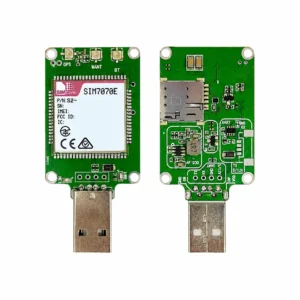
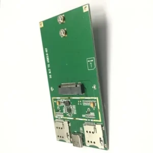
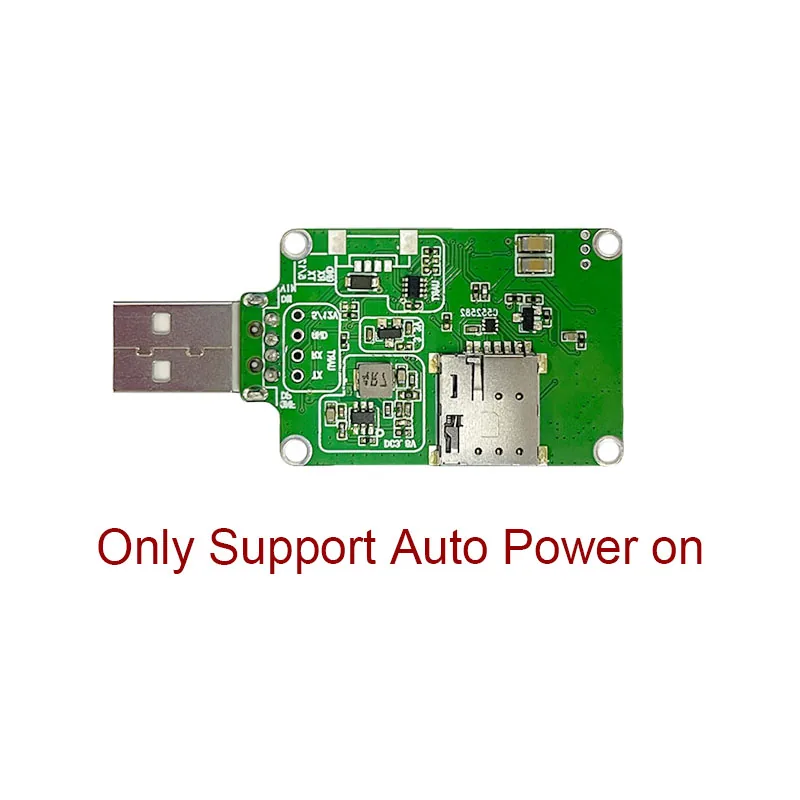
This page covers the USB Dongle PCB shown in the local 30&30 USB Dongle technical reference. It is a distinct 43.0 x 30.6 mm reference layout with USB-A, Nano SIM, UART test/interface pads and RF connector positions. It is not the 63.5 x 30 mm Micro-SIM board shown on the separate SIM7600-based board-revision page, nor a bare LCC module, M.2 card, Mini PCIe card or header development board.
The reference image shows the unpopulated reverse side and is marked auto-power-on only. It identifies the PCB form, not a confirmed production lot, supplied module, stock position or kit contents.
Documented compatible module configurations
Page 1 of the seven-page board reference lists compatible configurations across SIM7600, SIM7600-H and A7600 families, including documented regional variants of SIM7600E, SIM7600E-H, SIM7600G, SIM7600G-H, SIM7600NA, SIM7600SA, SIM7600A, A7600C, A7600E, A7608E-H and A7608SA-H. It also lists A5360E and A5360G under WCDMA. This is a compatibility list for the illustrated PCB platform; radio bands, GNSS capability, firmware and certification remain properties of the exact populated module and offered revision.
The source uses different generic product labels on different pages and does not provide one commercial PCB ordering number. Therefore this is a reference-platform enquiry page rather than a claim that every listed module is interchangeable or currently stocked.
| Mechanical reference | Page 2 drawing: 43.0 x 30.6 mm USB Dongle outline. Confirm the final drawing and tolerance for the offered PCB. |
|---|---|
| Host and service interfaces | USB 2.0, UART and Nano SIM are shown. The basic-parameter page states 1.8 V SIM support; UART is listed as 3.3 V by default and can support 5 V. |
| Power reference | The basic-parameter page lists 4-8 V VIN or 3.4-4.2 V VBAT. Do not apply that range to another PCB revision or power it before confirming the matched schematic. |
| RF and integration | The drawing shows RF connector positions and an antenna is required for the installed modem. Select the antenna, driver, SIM, firmware and host OS with the exact module configuration. |
| Documentation boundary | The board manual is a local technical reference, not a current approval, operator-acceptance record or finished-product certificate. |
Technical document and enquiry
Download the 30 x 30 USB Dongle technical reference (PDF). Confirm the complete populated-module P/N, PCB revision, board power connection, antenna option, SIM holder, cables and included accessories before ordering.
Request a quote with the chosen module P/N, destination network, host interface, required board revision and quantity.