

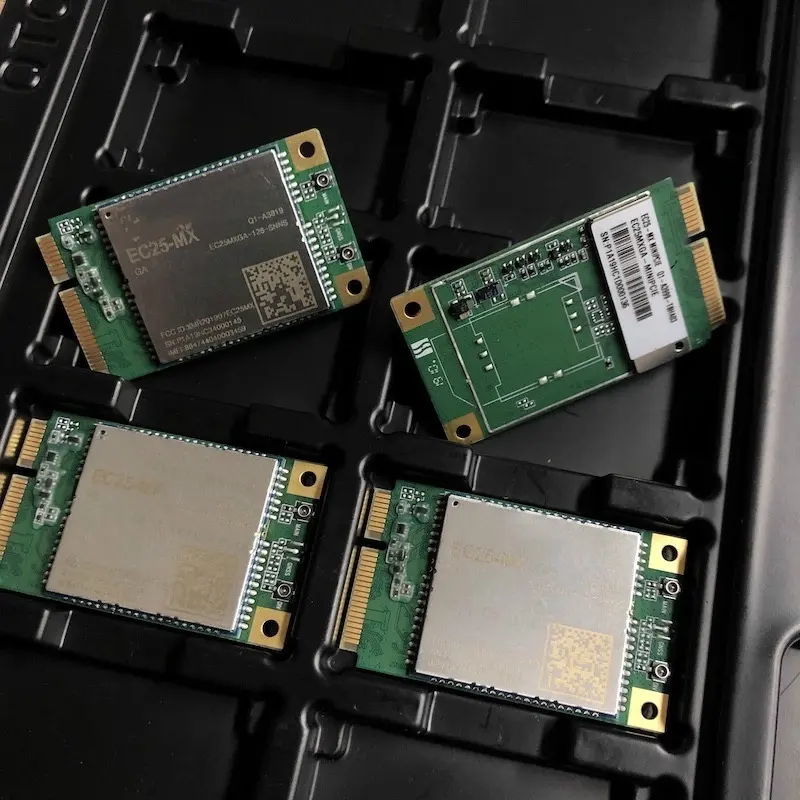
Choosing an EC25 module starts with the regional suffix and hardware form. A bare LCC module, a Mini PCIe card and a carrier-board assembly have different integration and power inputs. This guide connects EC25 current-consumption examples with the checks needed for retail, connected equipment and industrial monitoring.
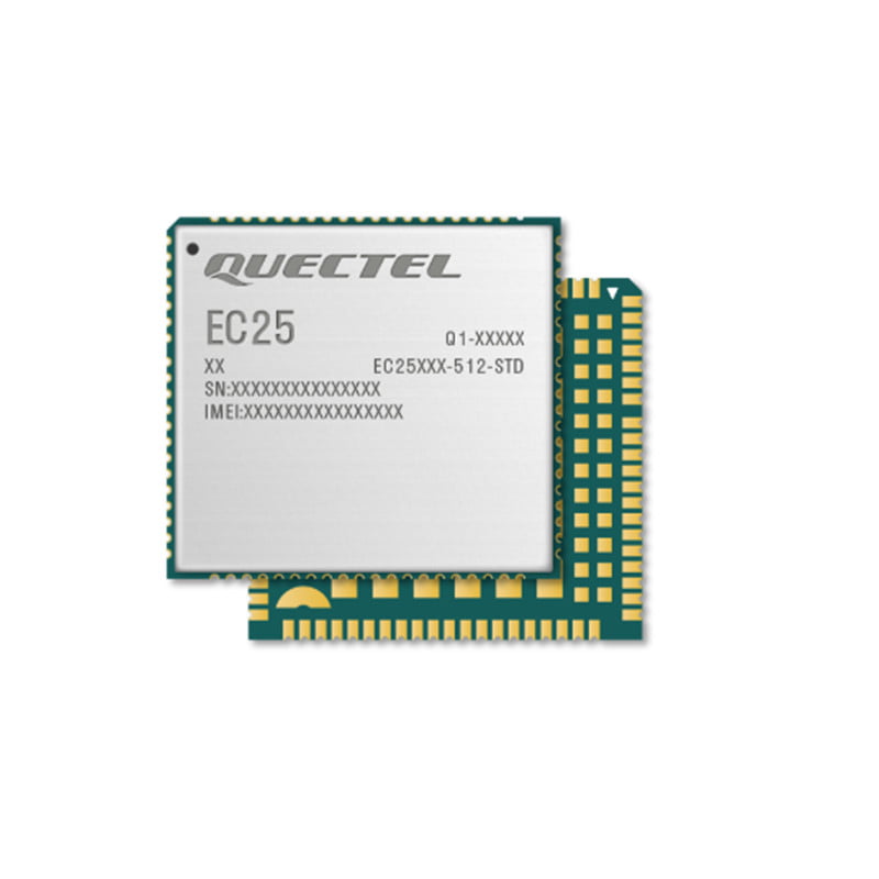
The bare EC25 family uses an LCC package measuring 29.0 x 32.0 x 2.4 mm. Quectel’s EC25 Series Hardware Design V2.4 lists maximum LTE-FDD rates of 150 Mbps downlink and 50 Mbps uplink, and LTE-TDD rates of 130 Mbps downlink and 30 Mbps uplink for supported variants. Compare the selected suffix’s bands and network modes with the intended deployment.
Use the full suffix when checking coverage. EC25 regional variants have different LTE bands and legacy-network support. The EC25 family product entry lists selected variants and links to the official documents. Check the country, operator and SIM plan against the exact part being ordered.
Check the main, diversity and GNSS RF paths in the hardware guide for the selected module. GNSS is an optional EC25 configuration. For a positioning application, confirm the ordered receiver option and antenna arrangement, then test acquisition and tracking in the planned installation.
Match the module firmware, exposed USB functions and driver package with the target host system. Verify modem discovery, data connection, suspend and resume on that configuration. For remote updates, document the supported update procedure and recovery path for the firmware being supplied.
Request the regulatory and operator approval documents for the full part number and destination market. Review the antennas, enclosure and integration conditions with the team handling finished-product compliance.
For connected equipment, make the communications requirement measurable: payload size, upload interval, acceptable delay, voice needs and recovery behaviour. Then check the radio, supply and software against that workload.
EC25 power consumption: read the conditions with the value
Quectel’s EC25 Series Hardware Design V2.4, Table 53 on printed pages 98-99, gives these typical EC25-AF values. Use them as a document reference when defining measurements for the selected hardware.
| EC25-AF state | Documented condition | Typical current |
|---|---|---|
| LTE sleep | LTE-FDD PF=128; USB disconnected | 1.8 mA |
| LTE idle | LTE-FDD PF=64; USB disconnected | 17.6 mA |
| LTE idle | LTE-FDD PF=64; USB connected | 29.4 mA |
| LTE data transfer | GNSS off; LTE-FDD B2 at 22.92 dBm | 698.0 mA |
The same manual lists 3.3-4.3 V, typically 3.8 V, at the bare module’s VBAT_RF and VBAT_BB inputs. Table 45 lists a 2.0 A maximum peak supply current under maximum power control on EGSM900; keep that 2G condition with the value. Use the separate card or assembly guide for a Mini PCIe or carrier-board input.
Measure voltage at the load during registration and uploads, record the band, signal conditions, firmware, USB state and GNSS state, and capture current over a complete reporting cycle. The cellular power-supply reset checklist explains the measurement setup and evidence to collect.
1. Intelligent Retail
For vending machines and self-checkout terminals, test transaction and telemetry requests with the intended SIM, operator and application backend. Peak modem throughput does not determine payment latency. Include reconnect behaviour, outage handling and firmware-download time in the terminal test plan.
2. Emergency broadcasting system
For a broadcast or alert terminal, define the required delivery delay and what happens when cellular service is unavailable. Test registration recovery, message acknowledgement, power backup and the alternative communications path required by the system design. Select the EC25 variant against those requirements.
3. Automotive industry
For connected vehicle equipment, confirm whether the quoted EC25 configuration includes GNSS and test the installed antenna layout and supply transients. EC25 Series Hardware Design V2.4 separates an operating range of -35 to +75 C from an extended range of -40 to +85 C. Match the applicable specification and thermal design to the selected hardware and vehicle installation.
4. Industrial monitoring
For remote equipment monitoring, measure coverage at the installation and define the reporting interval, payload and recovery delay. Buffer readings when the link is unavailable and test delivery after reconnection. Check enclosure temperature, antenna placement and module-input voltage under the site’s operating conditions.
Before requesting a quotation, record the full EC25 suffix, bare module or card form, destination operator, host interface, GNSS option and quantity. Include the reporting cycle and available supply measurements. Browse documents in the Datasheet Center or send the EC25 line in your BOM for a configuration review.