
Description
Hardware configuration
Mini PCIe modem adapter with a USB Type-A plug. Use this page to select an adapter or assembled modem for evaluation and host integration. Confirm the board and modem configuration with your quotation.
Photographs and supplied items
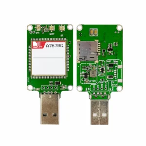
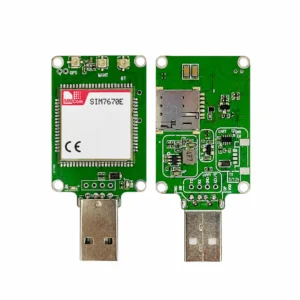
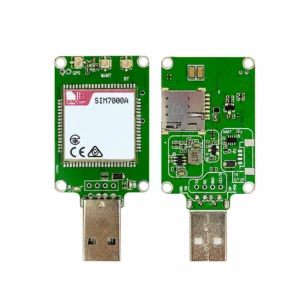
The front and reverse photograph shows a Mini PCIe card socket, retaining mechanism, USB Type-A plug, SIM holder and exposed pads. No installed modem or exact board part number is visible.
| Sales form | Mini PCIe modem adapter with a USB Type-A plug. Distinguish an unpopulated adapter from an assembly supplied with a modem. |
|---|---|
| Module / board identity | Order by complete module P/N and adapter revision, not by the generic 4G/5G title. Historical photos identify examples and do not establish current availability. |
| Kit contents | Specify board-only or board-plus-module, antennas, RF cables, SIM requirements, USB cable, enclosure and power accessories. Only the quotation establishes the included items. |
| Power and host | Obtain the board input rating, connector polarity, output rail, peak-current capability and host requirements before connection. |
| Network and performance | Determined by the installed module, firmware, antenna, SIM and network. An adapter does not add radio bands or certify operator acceptance. |
Integration checks
The original up-to-3 A and plug-and-play claims have no matched board rating or host validation. Confirm input power, regulated output and transient capacity. The adapter may require no separate driver, but the installed modem needs a supported driver and connection software.
Check mechanical clearance, cooling, antenna connectors, host driver version and application software before deployment. Do not insert or remove a module or SIM under power unless the matched instructions explicitly permit the operation.
Technical references
Minipcie to USB instructions.pdf is an undated six-page instruction sheet for a similar board. It identifies a Mini PCIe 52-pin USB signal path, USB 2.0 and a 65 x 31 mm board reference. Its illustrated component layout and SIM holder vary, so confirm the quoted board revision before using the schematic or test-point map. The text mentions a 3.3 V working rail; this does not mean that 3.3 V is the external USB input specification.
Request the applicable board specification, hardware instructions and compliance documents during enquiry follow-up. Adjacent-board manuals, module marks and historical family certificates do not establish the certification or tested performance of the quoted assembly. Current status and applicable hardware/software revisions require confirmation.
Related adapters and enquiry
Send the intended module, host model/OS, destination country/operator, quantity, connection requirements and accessory list with your BOM enquiry. Browse the Datasheet Center for related module references.